Your cart is empty
Reed Switches
PrintOPERATION INSTRUCTIONS
While the reed switch is in use, take precautions excepting any mechanical damages that lead to the seal failure of glass tube and damages of the leads.
The usage of ultrasound is not allowed for the reed switch cleaning and soldering.
The impact of ultrasound waves (10 to 250 kHz) on the reed switch can cause the change of Pull-In AT and Drop-Out AT or the tube break.
Care must be taken to prevent from any affect of the external magnetic field.
At switching of the electric circuits you must follow the maximum switching current values, the maximum switching voltage and power values within reed switch specifications as stated.
Stray inductance and capacitance should be taken into account.
To reduce their influence the load should be located within the close proximity of the reed switch.
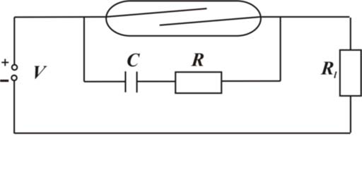
In case of no load, life time of a reed switch is 108. As the load increases the life time reduces. It is caused by erosion processes taking place on contact surfaces when reeds closeюopen. To enhance reed switch reliability protective circuits are recommended (Figs.1-4).
When using reed switches for resistive loads the contact protection is carried out with an RC-network.

Figure 1
To prevent arc striking the following condition must be fulfilled:
![]()
Where, Vr – reed blade voltage when the contacts are opened,V;
V – supply voltage, V;
R – resistance value, Ohm;
Rl – load resistance, Ohm;
Load resistance is calculated by:
![]()
Where,
Iswitch.max.– maximum switching current, А;
Il – load current, А;
The capacitance value is expressed by: С=(0,05...1,0)•Iswitch
Where,
С – capacitance value, μF
Iswitch – switching current, А;
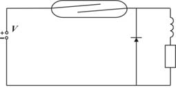
When using reed switches for inductive loads the contact protection is carried out with a diode

Figure 2
The rated current of the diode must not exceed the switching current.
The reverse rated voltage must not exceed the supply voltage V.
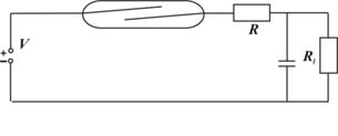
When using reed switches for capacitive loads the contact protection is carried out with a resistor (Figure 3).

Figure 3
The resistance value is calculated by:
R>=V/Iswitch.max.
Or
R>V2/Pmax.
Where,
Imax. – maximum switching current
Pmax. – maximum contact rating.
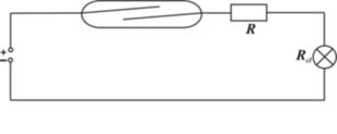
When using reed switches for lamp loads the contact protection is carried out with a resistor (Figure 4).

Figure 4
To reduce the high inrush current to Iswitch.max. value the following condition must be fulfilled:
R+Rcl = V/Iswitch.max.
Where,
Rcl-the cold lamp resistance which is at 8-14 times less than the hot lamp resistance
R – the resistance value


